Computers are built on (propositional) logic. The reason ( ) around “propositional” is that propositional logic is not the only choice of logic for computers. There are ternary computers based on 3-valued logic. (In 3-valued logic a statement can be either true, false, or neither.) In principle, you can build computers out of any $n$-valued logic. There are also computers based upon infinite-valued logic. Examples of such computers include fuzzy computers (based upon fuzzy logic) and quantum computers (based upon the laws of the quantum world!). There are so many interesting things to talk about these uncoventional computers but our discussion here is about conventional computers that are based upon propositional logic.
Computers carry out logical calculations. Arithmetic operations such as adding two numbers are in fact logical calculations as we will see later. Computers (conventional binary computers to be clear) can understand only the bits 0 (switch on-current) and 1 (switch off-no current). Hence everything in a computer is represented as patterns of of 0s and 1s. 0 and 1 can be understood as the two truth values, true and false, of propositional logic. For example, 0 could represent true while 1 does false. Using propositional logic one can design physical devices, called logic circuits, that perform intended results by producing bits (output) from bits (input). The design of logic circuits is called computer logic. The smallest units of a circuit are called the logic gates or gates in short, i.e. logic gates are building blocks of a logic circuit. Gates correspond to the operations of propositional logic, such as $\vee$, $\wedge$, $\oplus$, and $\neg$.
Example. The diagram of Or Gate.

Example. The diagram of And Gate.

Example. The diagram of Exclusive Or Gate.

Example. The diagram of Not Gate

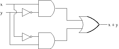
In practice, however, not all these operations are available to a circuit designer. For example, exclusive or can be performed using $\vee$, $\wedge$ and $\neg$ as we have seen here. $$x\oplus y\equiv(x\wedge\neg y)\vee(\neg x\wedge y)$$ The following figure shows a logic circuit that computes $x\oplus y$. The semi circle on a wire represents that the wire is crossing over another i.e. they are not connected.

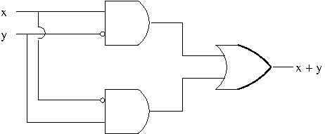
Not gate often simply represented by a bubble. With this convention, the above circuit can be simplified as in the following figure.

There is a very useful gate called NAND (NOT-AND) Gate. It is defined by nand operator $$p|q\equiv\neg(p\wedge q)$$ What’s interesting about nand operator is that any conventional operator can be expressed using only nand operator. For example, \begin{align*}\neg p&\equiv p|p\\p\wedge q&\equiv\neg(p|q)\equiv(p|q)|(p|q)\end{align*}
Example. The diagram of NAND Gate.

Binary Arithmetic
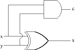
The basic rules of binary arithmetic: \begin{equation}\begin{aligned}0+0&=0\\0+1&=1\\1+0&=1\\1+1&=0,\ \mbox{carry}\ 1\end{aligned}\label{eq:binadd}\end{equation}As shown, when adding 1 to 1, the result is 0 but a 1 is carried into the next position to the left. For example,adding 1 to 10111 results in 11000 with three carries. $$\begin{array}{cccccc}& & 1 & 1 & 1 & \\& 1 & 0 & 1 & 1 & 1\\+& & & & & 1\\\hline & 1 & 1 & 0 & 0 & 0\end{array}$$ Here is another example $10101+01111$. \begin{equation}\begin{array}{ccccccc}& & 1 & 1 & 1 & 1 & \\& & 1 & 0 & 1 & 0 & 1\\+& & 0 & 1 & 1 & 1 & 1\\\hline & 1 & 0 & 0 & 1 & 0 & 0\end{array}\label{eq:binadd2}\end{equation} The question is how do we design hardware to do binary arithmetic? The simplest operation is the addition of two bits shown in \eqref{eq:binadd}. The equations in \eqref{eq:binadd} actually create two output bits, a sum $s$ and a carry $c$, from two input bits $x$ and $y$. The carry bit was not mentioned for the first three because it is 1 only when both input bits are 1. On the other hand, the sum is 1 only when one of the input bits is 1 and the other is 0. Hence, the device that performs the addition of two bits, called a half adder can be represented by the following diagram.

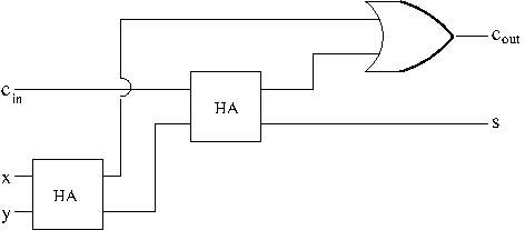
However, a half adder is not adequate to compute more complex binary sums such as \eqref{eq:binadd2} because when adding numbers with multiple digits we sometimes need three input bits. A full adder takes three input bits $X$, $Y$, and the carry-in bit $C_{\mathrm{in}}$ and produce two output bits, the sum $S$ and the carry-out bit $C_{\mathrm{out}}$. Th following is the truth table for computing the two output bits $S$ and $C_{\mathrm{out}}$ from the three input bits $X$, $Y$, and $C_{\mathrm{in}}$. $$\begin{array}{|c|c|c|c|c|}\hline X & Y & C_{\mathrm{in}} & S & C_{\mathrm{out}}\\\hline 0 & 0& 0 & 0 & 0\\\hline0 & 0 & 1 & 1 & 0\\\hline0 & 1 & 0 & 1 & 0\\\hline 0 & 1 & 1 & 0 &1\\\hline 1 & 0 & 0 & 1 &0\\\hline 1 & 0 & 1 & 0 & 1\\\hline 1 & 1 &0 & 0 &1\\\hline 1 & 1 & 1 & 1 & 1\\\hline\end{array}$$ The following diagram shows a way to construct a full adder using two half adders (represented by a box called HA). The circuit produces the sum bit by adding $X$ and $Y$ and then adding $C_{\mathrm{in}}$ to the result. The $C_{\mathrm{out}}$ is 1 if there is a carry from either the first or the second of these additions.

References.
[1] Essential Discrete Mathematics for Computer Science, Harry Lewis and Rachel Zax, Princeton University Press, 2019
